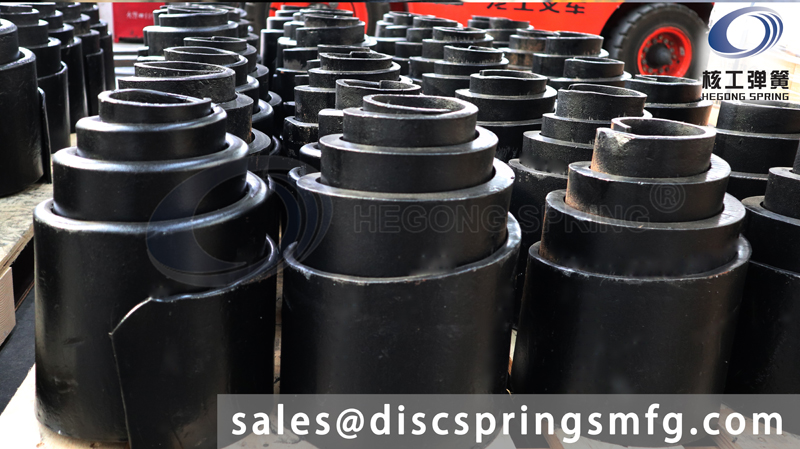
A volute spring was designed and tested by HEGONG DISC SPRING for use in launch restraint assemblies (LRA) on satellite deployables. The volute spring type was chosen because it offers a very compact stowed profile and a relatively long spring stroke compared to conventional wire compression springs. Test results showed that the output force was very predictable with the developed analysis and consistent with negligible change following exposure to thermal cycling, vibration environment, and low cycle life testing. Although the volute spring was ideal for this application, there are several lessons learned that should be considered before using this spring type, including the limited number of vendors willing/able to manufacture custom volute springs, high relative cost per unit, nonlinearity of the spring output force, high weight relative to wire compression springs, the criticality of the spring end configuration (unaltered vs. ground vs. closed) and the how it affected coil-to-coil frictional losses/build-up, and spring lubrication selection and migration during handling.
Springs are a simple and diverse component in many different types of mechanical systems. They can be used as mechanical energy storage devices, dampers, release devices and come in many different materials, shapes, and sizes. Each spring is designed to suit the needs of its system. One particular application for satellites, LRAs, requires a spring with a very compact compressed height and a very long stroke length. The most suitable candidate for this application was a volute spring but the supporting analysis and design background were not available.
The volute spring is manufactured from a relatively wide and thin bar or strip of spring material. The bar or strip is coiled around a mandrel such that each coil overlaps the adjacent coil forming a volute or cone. This process forms a tiered inner diameter, shown in Figure 1, which allows each coil to slide past the adjacent coil when the spring is compressed. The result is a spring that can be compressed to the initial width of the spring material regardless of the number of coils or stroke length the spring has. This is very convenient for space applications because it allows for significantly more output force and stroke versatility for a given volume than any leaf, coil, or torsion bar spring. Due to the overlapping strip material configuration, the volute spring also offers more stability than other spring types.
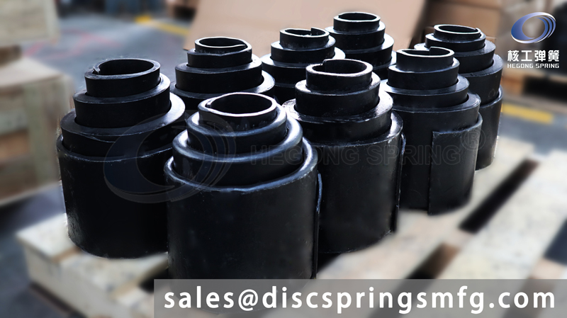
Figure 1. Volute Spring
Volute springs have been used in some terrestrial applications such as vertical and horizontal suspension systems for tanks and smaller tools like garden shears where a compact or self-guided spring is required. Since there are not a wide variety of applications that require the unique characteristics of a volute spring and the relatively high manufacturing cost, there are not as many off-the-shelf configurations that are considered vendor standard parts when compared to wire compression springs. This means that a detailed analysis and custom design is likely required for each application which contribute to the higher unit price of volute springs.
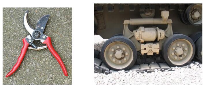
Figure 2. Terrestrial uses for volute springs
In general, aerospace applications have much more stringent requirements that require substantially more design margin than terrestrial applications. Custom design parts are frequently employed to meet these requirements as slightly more expensive mechanical piece parts can substantially reduce the system-level cost. One of the most critical requirements, for satellites in particular, is that the overall envelope of the spacecraft fits inside the launch vehicle fairings. The deployables and the LRAs that restrain them are generally at the very perimeter of this overall envelope which makes a compact design a requirement. The volute spring was ideal for this application for that reason.
Aerospace parts are upheld to a significantly higher standard than their terrestrial counterparts. Space environments such as extreme temperatures, vacuum, launch loading and payload restrictions often dictate special materials, processes and coatings. Furthermore, mechanical parts often require rigorous analysis to determine both output force margin and internal stress margins to ensure the adequacy of the design. As such, a solid understanding of the spring functions and analysis was required to justify its usage.
During compression, a volute spring essentially takes the applied axial load and bends the centerline of the spring bar downwards. The deflection begins at the largest coil of the spring which has the lowest spring constant. As the spring is compressed, the load is spread through subsequent coils until the point where the largest coil bottoms out, known as the initial bottoming load. After initial bottoming occurs, the load vs deflection curve changes from linear to exponential. This happens because spring force in each subsequent coil increases as the diameter of the coil decreases. This results in a curve that asymptotes at a peak high force at the solid height as shown in Figure 5. The point at which the smallest spring coil bottoms out is called the Final Bottoming Load. The peak of the Load vs Deflection curve is determined by the spring constant of the final coil because it is the stiffest coil in a standard volute spring.
Figure 3 illustrates the key parameters and variables required to perform the volute spring design analysis. The image on the right illustrates an unwound volute spring with ground ends. Based on the spring geometry parameters, the spring load, deflection, and stress can be calculated using the equations in Figure 4. The spring load is used to determine the force that the spring is capable of providing. The spring deflection equations are used to calculate how much the spring compresses axially under a known load. Lastly, the shear stress determines the internal stress in the coils when under an axial load.
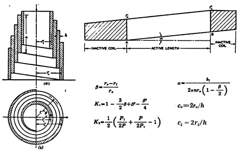
Figure 3. Key Parameters and Variable Definition [1]
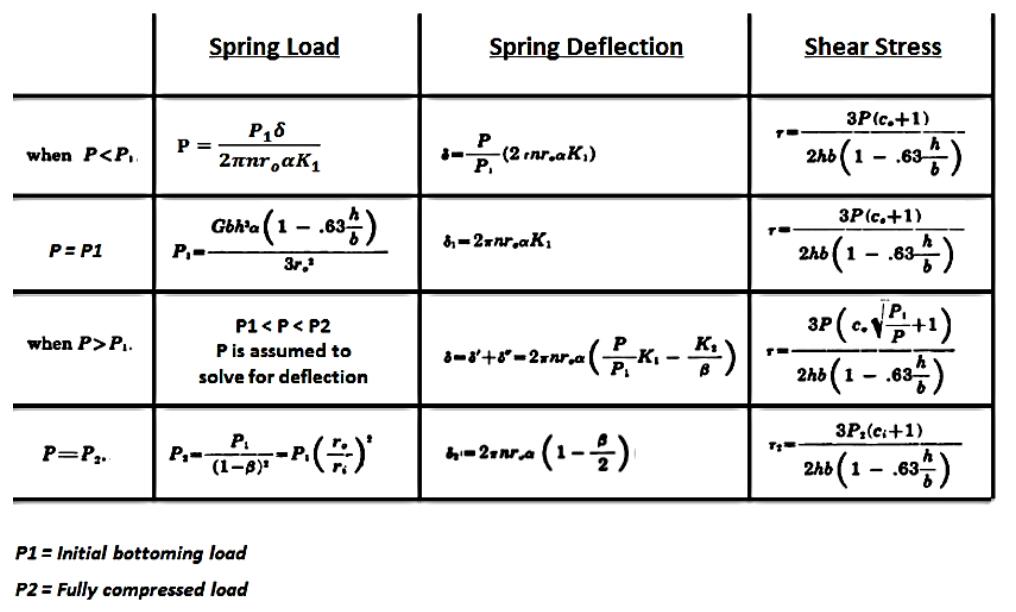
Figure 4. Volute Spring Load (P), Deflection (δ), and Shear Stress (τ) Equations [1]
Figure 5 is a theoretical load versus deflection curve for a volute spring. Initially, the spring has a linear force constant as the coils slide past each other under axial compression. At the point when the largest coil reaches the Initial Bottoming Load, the spring constant becomes exponential. This is because each following coil bottoms out in sequence, increasing the stiffness after each one. Finally, the smallest coil bottoms out and the spring is fully compressed.
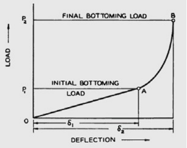
Figure 5. General Load-Deflection Characteristics of Volute Springs [1]
A number of different tests were performed to determine the whether the volute springs were both compliant to drawing requirements and acceptable for use in the spacecraft applications.
An Instron fixture with a motorized head (Figure 6) was used to generate the baseline spring force vs. deflection curve. The spring was set up in a simulated containment fixture and compressed to the stowed condition. The spring was then manipulated to relieve any frictional build-up to simulate a post-vibration deployment. The Instron head was then programmed to deploy the spring at a rate of 0.1 in/sec (0.25 cm/sec) to evaluate slip-sticking that may occur during the deployment. Following the deployment, the Instron head then compressed the spring at the same rate to the fully stowed condition. The spring force was recorded throughout this sequence. This test was repeated two more times to evaluate repeatability. As shown in Figure 7, the results proved to be very repeatable.
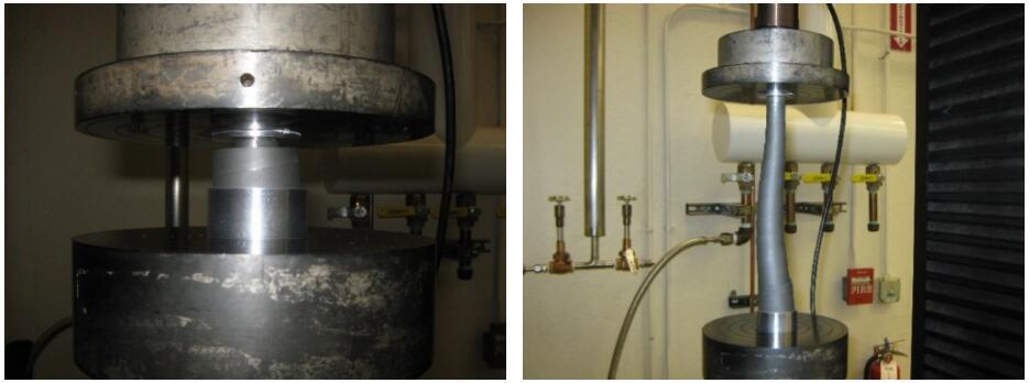
Figure 6. Instron Test Fixture for Load vs. Deflection Curves
The spring was then compressed and subjected to a random vibration environment. Following the vibration environment, the force vs. deflection test was repeated three more times to evaluate the effect of vibration on the spring force. As shown in Figure 7, the results proved to be very repeatable and in family with the baseline test results.
The spring was then compressed and subjected to ten thermal cycles from -100°C to +95°C. Following the thermal cycles, the force vs. deflection test was repeated three more times to evaluate the effect of thermal environment the spring force. As shown in Figure 7, the results proved to be very repeatable and in family with the baseline and post-vibe test results.
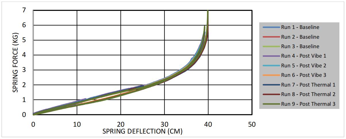
Figure 7. Volute Spring Force vs. Deflection Data
While the spring proved successful in the end, there were several drawbacks throughout the process that should be noted.
There was a limited selection of vendors that were willing and able to manufacture our custom volute springs. In the production of this spring, multiple requests were submitted but only two vendors were willing to quote. The first vendor lacked extensive experience with volute springs and they did not fully understand how the different spring parameters (inner coil diameter, helix angle, end configuration) affected the final spring force output curve. Their initial batch of springs produced a force vs. deflection curve that was significantly different than what was requested and they were unable to adjust the process or spring parameters to provide a spring that met the design requirements. The second vendor, who also had limited experience but displayed a much better understanding of volute springs, yielded better overall results. The test sample spring as well as the first three batches of springs all satisfied the design requirements with minimal dropout at the vendor.
The vendor's experience and understanding of how the volute spring parameters affect the characteristics of the design is the most critical factor in selecting a vendor. Choosing the right vendor will reduce the dropout rate which will ultimately reduce products overall unit price on future orders as well as the schedule risks associated with having to re-manufacture new springs.
The process for fabricating standard wire compression springs consists of feeding a wire into an automatic coiler which consistently and accurately sets the pitch and diameter of the spring. The process, which both vendors employed, to fabricate volute springs is much more labor intensive. Due to a lack of standard equipment/tooling, the vendors had to feed the strip material onto the rotating mandrel by hand, which made the process very workmanship dependent. This inherently will reduce the consistency of the spring characteristics on a unit to unit and lot to lot basis.
For large order quantities or anticipated reccurring orders, it is strongly recommended that the vendor develops a standard process/procedure and uses the appropriate equipment/tooling to reduce spring variation and overall dropout. For small order quantities or one time purchases, it is recommended that a standard process/procedure is used for manufacturing at a minimum.
Another critical issue encountered during the development process was the configuration of the ends of springs (unaltered vs. ground vs. closed) and how they affected the spring's overall performance.
The first configuration tested had unaltered ends which caused the spring to have rectangular points on the inner and outer coil (Figure 8) that interfaced directly with the adjacent parts. This resulted in an unstable deployment which caused the adjacent parts to cant. This is an undesirable situation because it makes the final deployed position less stable and less predictable. Another issue observed during testing was that the rectangular point on the end caused the inner, most powerful coil to begin expanding when the spring was being compressed. This caused an increase in friction between the inner coil and the adjacent coil. The increased friction had a negligible effect on output force when the deflection was small but as the spring got closer to the solid height, the impact grew exponentially. When the spring was close to the solid height, the other coils, all fully compressed, forced the inner coil closed to its original diameter. This caused excessive friction between the inner coil and the adjacent coil and the rectangular point on the inner coil and the fitting compressing the spring. This caused false output force readings of ~18 lb (80 N) on a spring with only ~3 lb (13 N) of potential. Although this did not affect the spring to the same degree in the deployment direction, it made it very difficult to get an accurate compressed output force measurement.
The second configuration tested had ground ends which removed the rectangular points that were causing issues with the previous test. This configuration was successful at mitigating the deployment stability issues as the spring now deployed straight and kept the parts oriented properly in the final position. However, while it was improved slightly, the ground-end spring still exhibited an unacceptable frictional build-up by the solid height due to the expanding inner coil.
The final configuration tested had closed ends with a full dead coil at either end (Figure 8). This configuration successfully solved all the issues discovered during testing of the unaltered and ground variants. Ultimately it provided a much more stable and repeatable deployment envelope and there were no indications of frictional changes at any point during the stow or deploy process. The reliability of the output force measurement significantly improved as well.
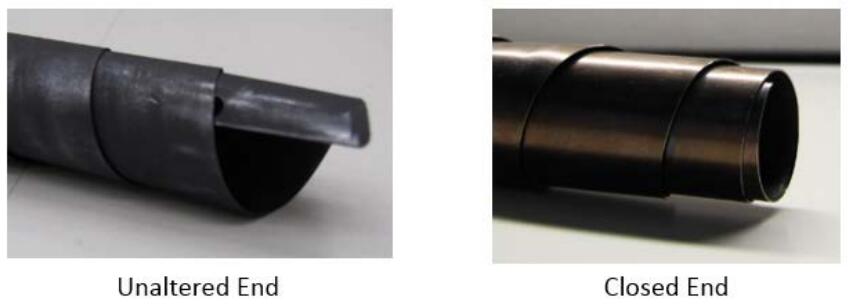
Figure 8. Unaltered vs. Closed Spring Ends
Based on the testing performed, it is highly recommended that all future volute spring designs specify that the ends be closed with a single dead coil on either end on the engineering drawing.
Two primary concerns from the beginning of the design processes were how the coil-to-coil friction would affect the overall output force of the spring and whether the coils of the spring could cold weld together when the spring is held compressed in a vacuum environment. A trade study was performed to determine the best options for lubricating the spring to reduce the impact and likelihood these concerns. Ultimately a sputtered dry film lubricant was selected since there was less concern of migration associated with wet lubrication and no concern of cracking/chipping/flaking during spring operation associated with hard coatings.
Instron testing was performed to determine deflection vs. spring force curves for both lubricated and unlubricated springs. The resulting data suggests that the lubrication had a minimal effect on the curve
under ambient temperature and pressure conditions. Both curves followed their analytically predicted curves and did not show signs of sticking. The unlubricated spring was also functionally tested in a TVAC
chamber to evaluate the risk of cold welding. Following thermal cycling from -100°C to +95°C in the compressed state, the spring was released at each temperature extreme. The following inspections showed
no signs of cold welding.
It is recommend that dry film lubrication be applied on springs to be used for space applications. The testing performed was not comprehensive enough to eliminate the need for lubrication. It did not evaluate the frictional effects on the output force at the temperature, pressure, and humidity of the space environment and it did not evaluate the likelihood of cold welding if the spring was held compressed for vibration/launch then held in a vacuum environment with no release in between.
While the volute spring may not be widely used terrestrially, they are ideal for space applications that require a spring with a very compact compressed height and a very long stroke length. The equations outlined in this paper, which were validated by test data, provide the means to design and analyze this spring and to verify force and stress margins. Testing also verified the volute spring performs consistently after exposure to hostile space environments. For future designs, leverage the lessons learned and recommendations herein to reduce the unit cost and schedule risk and increase the stability and reliability of the spring.
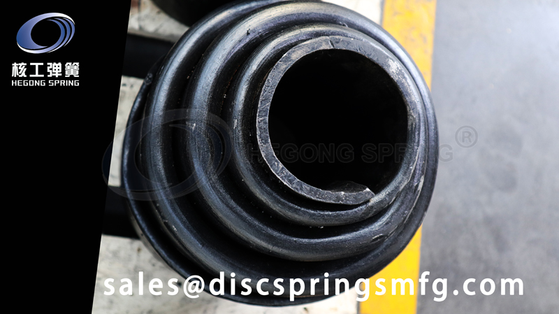
SHANGHAI HEGONG DISC SPRING MANUFACTURE CO.,LTD. (Hereafter called “HEGONG SPRING ®”) is a leading manufacturer in China specializing in designing and manufacturing of disc springs, disc spring washers, wave springs and various elastic elements. As leading company in the industry, HEGONG SPRING ® participated in drafting the standards of GB/T 1972-2005 (national standard for disc springs), JB/T 13296-2017(Wave Springs), JB/T 11698-2013 (Volute Springs) and JB/T 6655-2013 (High temperature resistant cylindrical compression springs).
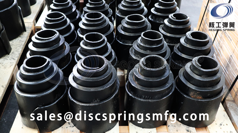
One order of Volute Springs for furnace application had been manufactured by HEGONG SPRING recently, height of volute spring is 300mm. The order has been completed, and the inspeciton results are good.
Product:Volute Spring
Material: 60Si2Mn
Application: Furnace
